Observing Meteors using GB3MBA
GB3MBA is the UK meteor beacon located at the Sherwood Observatory of the Mansfield and Sutton Astronomical Society. It's construction, by volunteers, was funded by the Radio Society of Great Britain and its running costs are supported by the British Astronomical Association.
The beacon transmits a CW signal vertically up using circular polarisation to illuminate the region where meteors entering the earth's atmosphere burn up briefly creating ionisation reflective to radio. This occurs at an an altitude of 80 to 100km. The beacon “illuminates” a region with a diameter of about 400km centred on it's location near Mansfield.
You can make observations of meteors entering the earths atmosphere a large part of the UK by viewing the projects' network of receivers which are streamed live here See using the live Streams for more information here. If you want to use or make your own receiver for GB3MBA please read on.
- Receiver Requirements
- Antennas
- Noise and interference
- Making observations
- Science Objectives
- Example Observations
Receiver Requirements
In principle, any receiver covering the required frequency of 50.408MHz, connected to a suitable antenna can be used to receive meteor echoes. Those within about 400km of the beacon can expect to see reflections from aircraft too but these are easily distinguished from meteor events. Other, naturally occurring phenomena within the ionosphere can also cause reflections which can be observed at even greater distances from the beacon but again, with some care the observer can distinguish these from meteor events. Meteor echoes will be detectable up to about 1200km from the beacon depending on the performance of the receiver and antenna. As with most aspects of radio astronomy, man made interference can be a problem so before investing too much time and money it is wise to conduct some simple tests at your location to see whether the local noise level is acceptable. See “Noise and Interference” for more information on assessing your local interference level.
While a conventional receiver can be used, a Software Defined Radio is a better option and if starting from scratch this will be cheaper too. A conventional receiver should be tuned to 50.407MHz, 1KHz below the beacon frequency, and using Upper Side Band (USB) will produce an audio signal centred on 1KHz which can be displayed on an audio spectrogram such as Spectran to study the size and “shape” of the echoes.
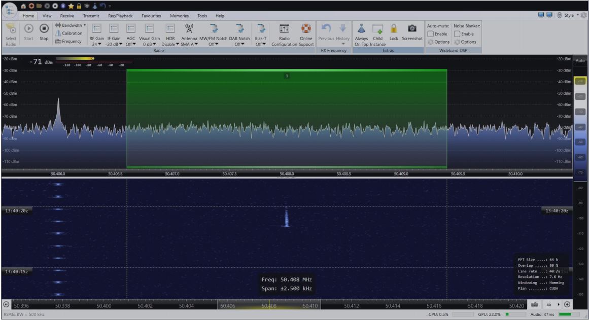
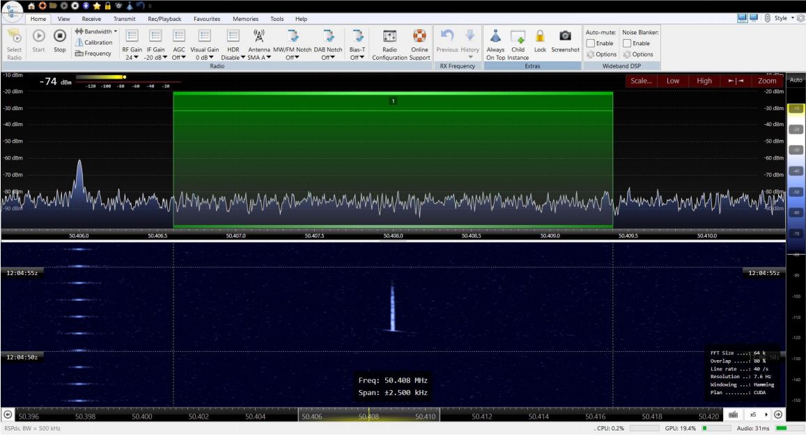
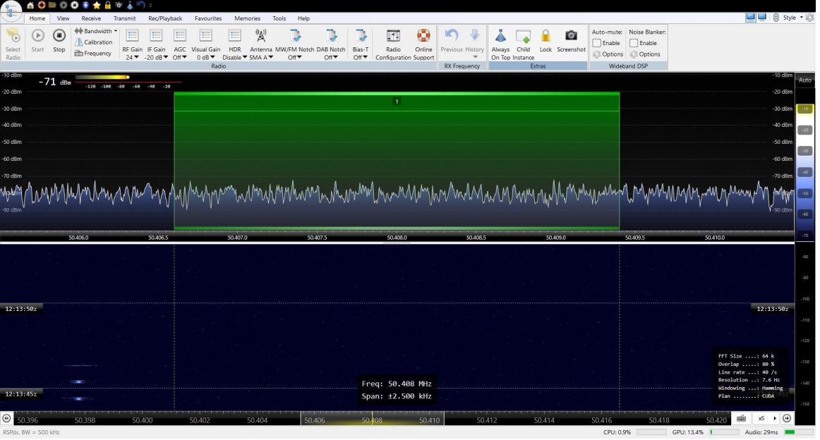
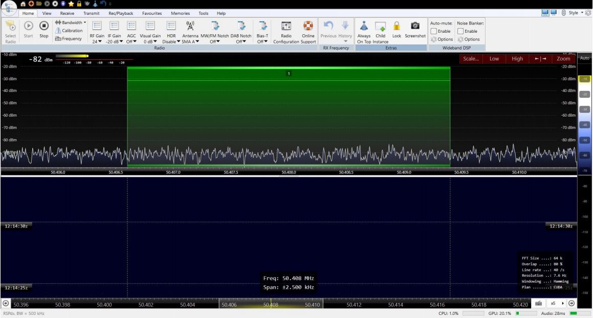
The best solution however is to use a Software Defined Radio together with software to display the spectrum and having a waterfall display (See Screenshot 1).
There are many SDRs available on the market and many software packages to support them. An important part of this project is to develop a network of receivers accessible to all. After we have built and deployed the first few receivers we will publish the design and it is hoped that others will build their own receivers and join them into the network. Whilst for casual observations almost any receiver will do, to join the network receivers will have to conform to our standard and be deployed to suitable, radio quiet locations with power and internet access. Those without suitable locations will be able to access our network of receivers to make their own useful observations.
Our design is based on the RSPdx from SDR play and these notes will focus on how this receiver can be used, initially using SDR Console as the display, to make very useful initial observations which will contribute to the project. When the network is developed, users will in principle, be able to use any suitable software to record, display and analyse echoes from GB3MBA as received by our network of receivers. Once you start making detailed observations and want accurate measurements of Doppler shift it becomes necessary to provide a precision frequency reference. The RSPdx has the ability to accept a 24.00000MHz reference and this can be provided by a Mini Precision GPS Reference Clock. See Fig 1.

But to get started with a system that will be able to join the network, all you need is an RSPdx, a suitable antenna and a PC. Using SDR console you will be able to check your location for local noise, position your antenna for best results and see your first echoes from GB3MBA. See screenshot 1. Visit the Resources – Documents section of this website for further information.

Antennas
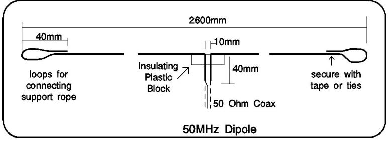
If you are within about 200km of the beacon, you can get started with a simple wire dipole. See Fig 2.
Try positioning the antenna away from noise sources and if the direct signal from the beacon is strong try placing the antenna end on to the direction of the beacon where there is a null in the dipole's doughnut shaped radiation pattern.
A popular choice of antenna is the Moxon type see Photo 1. This is more compact and robust than a 2 element Yagi antenna and has an exceptionally high front to back ratio which can be useful to null out local noise sources. This can be constructed from wire and plastic water pipe for just a few pounds see Building a moxon antenna or can be purchased from Wimo Antennas Photo below If you want to make your own more robust version like the Wimo one using aluminium tube the Moxon Rectangle Calculator by AC6LA does all the maths for you see Moxon Rectangle Calculator.
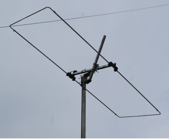
These antennas have a useful gain and a very high front to back ratio which can be used to null out local noise sources.
Within 200-400km of the beacon you can expect to see aircraft reflections in addition to meteor echoes. From 400km to about 1200km echoes from meteors and from other phenomena that occur in the ionosphere such as Sproradic E will be observed. You will learn to distinguish between meteor echoes and these unwanted ones if you follow these notes.
Directional antennas such as the Moxon, should be pointed up, towards the point 100km above the beacon. Close to the beacon your receive antenna should be pointed vertically up.
Try different configurations to find out what works best for you by “nulling” out the direct signal and / or interference.
If you are located more than about 400km from the beacon an antenna with more gain may be helpful such as a 3 or 4 element Yagi.
Noise and interference
Man made noise and interference is the bane of all radio astronomers. If you are lucky enough to live in a radio quiet rural area or one where the interference is minimal you will have few problems. It is useful to asses your local noise level before you spend too much time, money and effort. This can be done with any SDR using SDR SDR Console to compare the “noise Floor” with antenna connected to that with the antenna replaced by a 50 Ohm load as described here.
Making observations
Once you have established that you can receive meteor echoes from the GB3MBA beacon you will need to consider how to display them. For simple meteor counts, a slow waterfall display with a narrow frequency span is adequate.
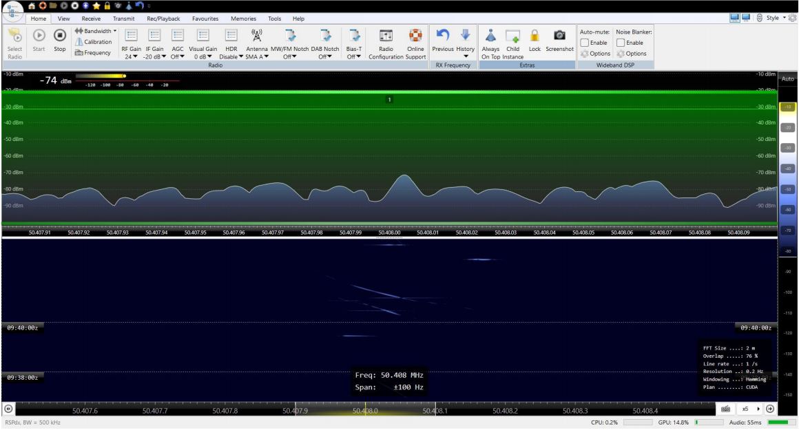
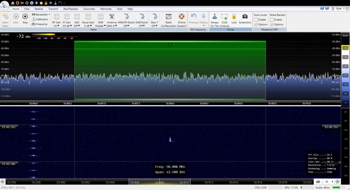
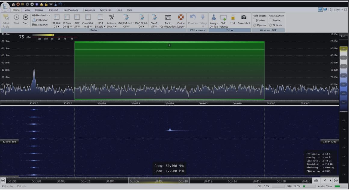
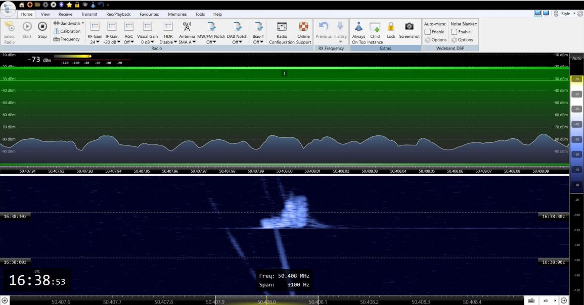
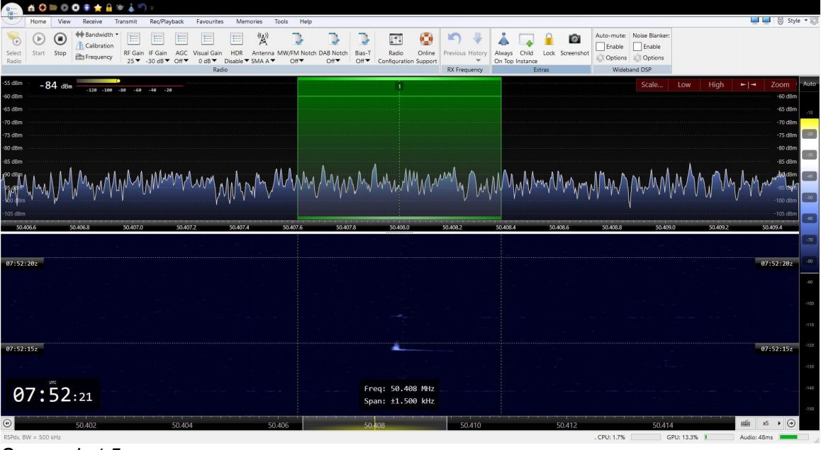
The presence of a “head echo” confirms that we are viewing a meteor ( or space debris ) event. Other ionospheric phenomena such as sporadic E can give rise to echoes which will not feature a head echo and could otherwise be confused with meteor echoes.
Science Objectives
Details of the projects science objectives can be found at:- Science Objectives
Some additional detail we wish to collect and study include:- Brightness and extent of Doppler shift of the head echo. Note that “Head echoes” are most probably directional so not all observers of a particular event will see one.
Head echoes are from a thin, short, wire like structure they may be directional and polarised. This is an area of particular interest. Later in the project we plan to use observation of precise Doppler shift at an instant, viewed from multiple directions, to calculate the location, trajectory and radiant of meteor events. Also it should be possible to establish the altitude at which maximum ablation occurs and / or where tail echoes form.
Example Observations
While our network of receivers is being developed and deployed useful observations can be made using your own receiver together with software such as SDR Console and that is what I have used to produce the examples I show here. SDR Console is free ( but please make a donation to it's author if you use it )
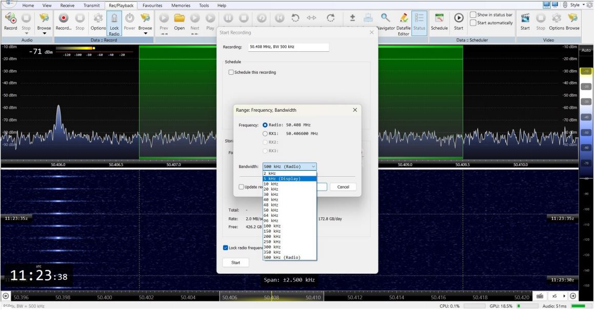
Screenshots with the high resolution, fast waterfall ( say 10 seconds maximum ) and wide span ( say +/- 2.5KHz ) will be very helpful. SDR Console can also make useful compact recordings by setting the range to “Display” the span you have set. See Screenshot 6.